power door lock wiring diagram?

2001 FORD TRUCK
73,000 MILES • V8 • 4WD • AUTOMATIC
Avatar
RUSSPOINT
  • MEMBER
  • 2 POSTS
Both sides quit at the same time. They will not operate either from the inside rocker switch or from the key fob. When trying the key fob , the interior light goes on when using the unlock. The horn will honk when using the lock. I can hear an audible click from under the dash whenever the key fob or the inside rocker switch is operated. I sounds like a relay is operating, but nothing is going to the door locks to operate them.
Feb 19, 2009 at 4:02 PM
Advertisement
Avatar
DAVE H
  • CERTIFIED EXPERT
  • 13,384 POSTS
TEST B: ALL POWER DOOR LOCKS INOPERATIVE 
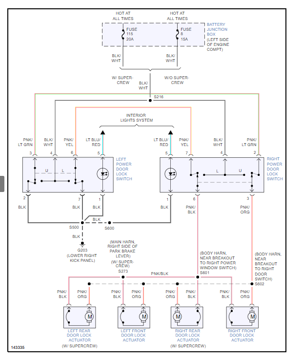
Turn ignition off. Disconnect right power door lock switch. Measure voltage between ground and door lock switch harness connector terminal No. 4 (Black/White wire). See Fig. 1 . If voltage is greater than 10 volts, go to next step. If voltage is not greater than 10 volts, repair Black/White wire. See WIRING DIAGRAMS . Retest system operation. Ensure right power door lock switch is disconnected. Disconnect left front door lock actuator. Measure resistance between right door lock switch harness connector terminal No. 6 (Pink/Black wire) and left front door lock actuator harness connector circuit No. 117 (Pink/Black wire). If resistance is less than 5 ohms, go to next step. If resistance is not less than 5 ohms, repair Pink/Black wire. See WIRING DIAGRAMS . Retest system operation. Ensure right door lock switch and left front door lock actuator are disconnected. Measure resistance between right door lock switch harness connector terminal No. 3 (Pink/Orange wire) and left front door lock actuator harness connector circuit No. 118 (Pink/Orange wire). If resistance is less than 5 ohms, go to next step. If resistance is not less than 5 ohms, repair Pink/Orange wire. See WIRING DIAGRAMS . Retest system operation. Reconnect left front door lock actuator. Ensure right door lock switch is still disconnected. Disconnect left door lock switch. Measure resistance between left door lock switch harness connector terminal No. 6 (Pink/Yellow wire) and right door lock switch harness connector terminal No. 7 (Pink/Yellow wire). Measure resistance between left door lock switch harness connector terminal No. 3 (Pink/Light Green wire) and right door lock switch harness connector terminal No. 2 (Pink/Light Green wire). See Fig. 1 . If resistance is less than 5 ohms in either test, replace suspected door lock switch. Retest system operation. If resistance is not less than 5 ohms in either test, repair Pink/Yellow or Pink/Light Green wires. See WIRING DIAGRAMS . Retest system operation. 
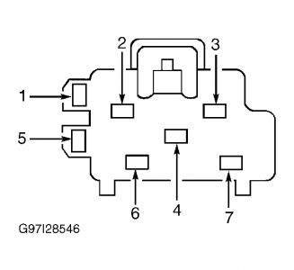
Fig. 1: Identifying Door Lock Switch Harness Connector Terminals


https://www.2carpros.com/forum/automotive_pictures/266999_door_6.jpg

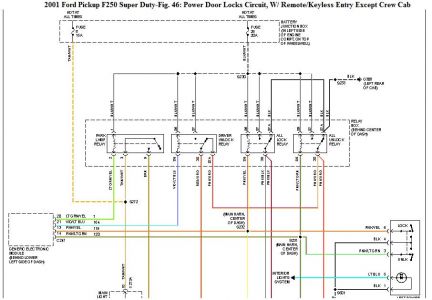
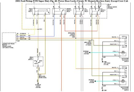
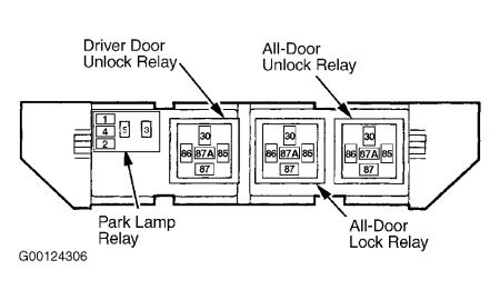
Check out the diagrams (Below). Please let us know what happens.
Feb 19, 2009 at 4:18 PM
Avatar
RUSSPOINT
  • MEMBER
  • 2 POSTS
Started diagnostics. No power to right side pin 4. No wiring diagram to be able to trace out. Is there another relay somewhere under the dash I should be looking for??

Russ
Feb 20, 2009 at 11:47 AM
Advertisement
Avatar
DAVE H
  • CERTIFIED EXPERT
  • 13,384 POSTS


https://www.2carpros.com/forum/automotive_pictures/266999_2502_1.jpg


https://www.2carpros.com/forum/automotive_pictures/266999_250_1.jpg

Feb 20, 2009 at 1:17 PM
Avatar
DAVE H
  • CERTIFIED EXPERT
  • 13,384 POSTS
I have supplied You with the wrong test sequence .. this is the test's with keyless entry and the wiring diagram is correct !! sorry .. Ignore my first post on do these test's TEST B: ALL DOOR LOCKS INOPERATIVE FROM DRIVER DOOR LOCK CONTROL SWITCH Turn ignition off. Disconnect driver door lock control switch connector. Measure resistance between driver door lock control switch harness connector terminal No. 1 (Black wire) and ground. See Fig. 3 . If resistance is less than 5 ohms, go to next step. If resistance is not less than 5 ohms, repair open circuit in Black wire. See WIRING DIAGRAMS . Retest system operation. Ensure driver door lock control switch is disconnected. Remove all-door lock relay from RKE relay box. Measure resistance of Pink/Yellow wire between driver door lock control switch harness connector terminal No. 6 and all-door lock relay cavity No. 86. See Fig. 3 and Fig. 4 . If resistance is less than 5 ohms, go to next step. If resistance is not less than 5 ohms, repair open circuit in Pink/Yellow wire. See WIRING DIAGRAMS . Retest system operation. Ensure driver door lock control switch is disconnected. Install all-door lock relay and remove all-door unlock relay from RKE relay box. Measure resistance of Pink/Light Green wire between driver door lock control switch harness connector terminal No. 3 and all-door unlock relay cavity No. 86. See Fig. 3 and Fig. 4 . If resistance is less than 5 ohms, replace driver door lock control switch. Retest system operation. If resistance is not less than 5 ohms, repair open circuit in Pink/Light Green wire. See WIRING DIAGRAMS . Retest system operation. Fig. 3: Identifying Door Lock Control Switch Harness Connector Terminals


https://www.2carpros.com/forum/automotive_pictures/266999_4_8.jpg


https://www.2carpros.com/forum/automotive_pictures/266999_5_6.jpg

Feb 20, 2009 at 1:29 PM