While driving engine shuts off

1995 PONTIAC GRAND AM
240,000 MILES • 2.3L • 4 CYL • 2WD • AUTOMATIC
Advertisement
Avatar
YASIRDAHHAM
  • MEMBER
  • 186 POSTS
It is late night now. I did some test to check continuity for the 3 pins of the connector of the pressure switch/fuel pump control switch of my car. As you can see, it is a 3-wire connector to fit the 3-pins pressure switch attached to my cylinder head end . The colors are pale but look like (red- pink and brown).The brown wire gave no electricity as you can see in the images attached to this comment and what follows it, the rest of wires gave a (live) test but one wire made the test tool glow like a sun while the other made it glow faintly.
Jun 12, 2021 at 2:41 PM
Avatar
YASIRDAHHAM
  • MEMBER
  • 186 POSTS
The 2nd test pin.
Jun 12, 2021 at 2:42 PM
Advertisement
Avatar
YASIRDAHHAM
  • MEMBER
  • 186 POSTS
The 3rd and final test pin.
Jun 12, 2021 at 2:42 PM
Avatar
JACOBANDNICKOLAS
  • CERTIFIED EXPERT
  • 110,175 POSTS
Hi,

I dug through several schematics and finally found the one with a 3 wire oil pressure switch. According to the schematic, the wires are pink, gray, and tan. Tan goes to the IP, so that shouldn't have power as you mentioned. The pink wire is powered via a 20 amp pump/injector fuse and should provide 12v (bright light) when the key is in the run position. The gray wire should also have 12v when the fuel pump relay and oil pressure is present, but nothing, when there is no pressure and the relay, is not actuated. You are getting a small amount of power there. Something is shorting to the gray wire. Trace the gray wire back to the fuel pump relay and check for a short to power. Or, the fuel pump relay is bad. Remove the relay and inspect the pins in the box. Check the relay. Here is a link that explains how it's done:

https://www.2carpros.com/articles/how-to-check-an-electrical-relay-and-wiring-control-circuit

If the tan wire was cut, that will prevent the gauge from working. Also, it won't bypass the oil pressure switch's signal for the fuel pump to work or not to work.

See pics below. The pictures are from General Motors (Pontiac Division). I'm hoping the wire colors you are seeing match.

Let me know.

Joe

See pics below.
Jun 12, 2021 at 8:41 PM
Avatar
YASIRDAHHAM
  • MEMBER
  • 186 POSTS
This is a great dispatch! I will take some time to go through the 3 attachments comparing the wires to my own, and yes it is (tan) color, I used the (brown) instead, I apologize for that, I am attaching a daytime photo for the 3 wires, the colors are pale since these are the original wires for a 26 years old automobile so I cared to make the connector visible too. I am so grateful for the great assistance you are providing, such a wonderful site that I needed to get acquainted with so long ago.
.
Jun 13, 2021 at 12:06 AM
Avatar
YASIRDAHHAM
  • MEMBER
  • 186 POSTS
Alternatively, when I dismantled the whole dashboard some 2 weeks ago and came out with that blue controller for chimes, I found one loose connector that is like a lone wolf, no mating part to find around the location where it was hanging down to the right side of the DLC and a bit deep near to the front side of the compartment . Any idea what is it? Does it relate to any component, controller or relay may be? I am attaching two other images for the DLC of my car, it had no live power in any of the 3 wires, hence the (no communication with scanner) that I used to get every time I be scanning through the DLC.
Jun 13, 2021 at 12:15 AM
Avatar
JACOBANDNICKOLAS
  • CERTIFIED EXPERT
  • 110,175 POSTS
Did the vehicle come with a factory alarm? I believe that is a connection for it. The one wire appears orange, is that correct? The other two is one blue? It looks damaged in the pic, and the last one gray or tan?

As far as the DLC, those are the correct color wires. The black one with a white tracer should have continuity to ground. See pic 1 below.

Pic 2 below shows the data link connector, identifies each pin and shows locations. I highlighted the ones relevant to your vehicle. This is an OBD1 system. Here is a link that explains how to retrieve codes.

As far as an OBD1 system, they usually didn't supply power. Do me a favor. Follow the link below and let me know if you get codes. All you need to do this is a short jumper wire or even a paper clip. Here is the link. You will be jumping pins A and B. See directions.

https://www.2carpros.com/articles/buick-cadillac-chevy-gmc-oldsmobile-pontiac-gm-1983-1995-obd1-code-definitions-and-retrieval-method

Let me know if you get anything via that method. Also, please make sure the wires to your DLC are taped with electrical tape or shrink wrap. You don't want them shorting out and they look a bit rough. Also, if you get no signal via the check engine light, confirm you have continuity to ground via the black wire with the white tracer.


Take care,

Joe


Jun 13, 2021 at 6:01 PM
Avatar
YASIRDAHHAM
  • MEMBER
  • 186 POSTS
1- My car doesn't seem to have any alarm option, so the 3-wire male connector is not important as it looks an "extra accessory" here. The colors are (Orange=Blue- Grey if not tan as you described it, it is a pale color tone ). 2- The black with a white tracer wire pin in my DLC had a positive continuity test with ground. 3- Is ALDL the alternate term for DLC? 4- The link you provided: I once read this content but not that detailed as it is here. It would have been a great great thing to use but since my DLC doesn't have any pin/wire in the (B) terminal, how can I jumper it to the adjacent(A) terminal?
Jun 14, 2021 at 12:54 AM
Avatar
YASIRDAHHAM
  • MEMBER
  • 186 POSTS
Awaiting your next reply I checked the Coolant Temperature Sending Unit ( to ECM), it has only one wire attached to its connector, another orphan wire is dangling right behind the engine and since I had replaced the Oxygen Sensor and attached it to the other dangling wire right there so the one left has been taken by me as relevant to the Coolant Temperature Sender Unit especially that it has 2-pins and its connector also has 2 pins. Am I right with that? I am trying my best to help myself amending all other faulty locations that might be relevant to the engine stalling, it has been a non-stop act so far. The attached images are(in sequence): My old Coolant Temperature Sender unit and the old connector with 1 wire only- The old and the replacement Coolant Temperature Sensor Units, they look the same both having a stamping of ( AC - 12 V) but the numbers facing the camera differ - The old Sender Unit connector ( with one wire only, the other wire has been cut off by an earlier mechanic work, only a few millimeters left of it- i soldered it to a piece of wire so the connector now has 2 wires to match the 2-pins Sender Unit).
Jun 14, 2021 at 7:58 AM
Avatar
YASIRDAHHAM
  • MEMBER
  • 186 POSTS
Dear Joe,

You started with a diagram for that grey wire connections (attached here) . The schematic diagram turned out to be for a (2-wire Oil Pressure Sensor/Connector) so you kindly started sending me 100% relevant schematics as to my very case of a 3-wires connector and sensor. The first schematic you sent (despite being for a 2-wire connector) had a beautiful tracking of the grey wire but it would then disappear at the top of the diagram, I needed to know where would that line for the grey wire be going since I have a grey wire coming from behind the engine to reach the Fuel Pump Relay but it is a dead wire with no voltage (this is the reason my electrician bypassed the ECM and fed the Fuel Pump Relay line via the ABS relay since it is a switch-live point- Sometimes we went as far as feeding the Fuel Pump relay via the hot end of the car battery to escape sudden stalling) . thought to be the same grey wire so I need to track it ( from the Oil Pressure Sensor connector all the way till it reaches the Fuel Pump Relay and the ECM, I need to check where the hell does it get dead. Can you provide that, with due gratitude and thanks for your invaluable information?
Jun 14, 2021 at 8:39 AM
Avatar
DANNY L
  • CERTIFIED EXPERT
  • 5,648 POSTS
Hello again.

One thing I would do is fix the connector from a prior post you attached a connector picture of. This connector as you can see have frayed-exposed and possibly burnt-melted sheathing and connections. This could not be possibly providing not only a good signal but also possibly improper voltage causing issues like you are experiencing. You should repair this immediately. I've attached the said picture below and circled in red. Hope this helps and thanks again for using 2CarPros.

Danny-
Jun 14, 2021 at 7:24 PM
Avatar
YASIRDAHHAM
  • MEMBER
  • 186 POSTS
An advice in its most proper timing, I had been thinking of replacing it since I have another one but for some stupid reason i postponed that. I sensed what you are telling here once comparing the colors, while Joe referred to one of the 3 wires as (pink) it is here almost a ghost wire with no defined color. Seems like heat and aging had done a lot to this connector. I will replace it right now as I am in the midst of replacing the Coolant temperature Sending unit along with its connector and the other connector pertaining to the Coolant temperature Sensor, all neighbors as you surely know. Thank you dear Danny, a big thank you
Jun 14, 2021 at 11:25 PM
Avatar
DANNY L
  • CERTIFIED EXPERT
  • 5,648 POSTS
Hello again.

Just keep us updated as to progress being made or anything you find. We are here to help. Thanks again for using 2CarPros.

Danny-
Jun 14, 2021 at 11:53 PM
Avatar
YASIRDAHHAM
  • MEMBER
  • 186 POSTS
I have already replaced the bad connector. this is the image for them both, you can see how what I called as Brown was indeed pink but so it looks (looked) to me.
Jun 15, 2021 at 12:51 AM
Avatar
DANNY L
  • CERTIFIED EXPERT
  • 5,648 POSTS
Hello again.

Keep up the good work! Keep us updated. We're always here to help. Thanks again for using 2CarPros.

Danny-
Jun 15, 2021 at 8:02 PM
Avatar
YASIRDAHHAM
  • MEMBER
  • 186 POSTS
Hi dear Danny,

Updating my car's stalling issue. It's been a few days since we last exchanged ideas and suggestions regarding this malfunction and I have been driving my car without stalling. The last thing(s) I ever made was cutting off that irksome and battered connector for the Fuel Pump Control/Oil Pressure Sensor and attaching a better one as well as replacing the Coolant Temperature Sender. Since I had no way of testing the latter, I simply replaced it using another sender for an Oldsmobile Cutlass Sierra engine, one that looked almost the same. Also, the Coolant Temperature Sensor had a connector with only one wire, the second (blue color) had been cut off by one reckless mechanic, I soldered a dangling wire behind the engine to that connector and also replaced the Oxygen Sensor as well as attaching its wire, another dangling wire behind the engine. the car mechanics I sought advice from all didn't have any idea about the first dangling wire, your interaction and support encouraged me to take the lead and reach out for those hard to reach places dismantling whatever came in front of me (coolant hose, intake air filter cover, harnesses for Ignition assembly and vacuum hose from brake assembly to intake manifold). I am testing the engine for a prolonged period this time, once I make sure all is okay. I will be sealing this thread with a final update ( he Check Engine yellow light is still on but since the DLC does not offer any way of reading data I am dropping this light for now. all I want is forget about those embarrassing stalling cases.
Jun 18, 2021 at 6:48 PM
Avatar
YASIRDAHHAM
  • MEMBER
  • 186 POSTS
Day 1: The stalling occurred again after a 3 days break! Just how can it be okay for 3 days driving some 20-25 km each day and then the engine gets back to its malfunctioning status? Is it the ECM/PCM?
Jun 19, 2021 at 3:27 AM
Avatar
YASIRDAHHAM
  • MEMBER
  • 186 POSTS
Joe: Kindly acknowledge: How/where to get a wiring schematic of the A/C relay? It used to work alright but today the thin red/pink wire that used to be (live) is dead now, only the blower works while the A/C compressor doesn't. The electrician used a short wire to get 12 VDC to the relay and there it worked, the A/C compressor engaged its clutch and it worked. he needs a wiring diagram to trace the relay wire and see where did the transition happened.
Jun 19, 2021 at 10:33 AM
Avatar
YASIRDAHHAM
  • MEMBER
  • 186 POSTS
One question please. what are these three (seemingly) metal fuses extreme right of the Fusebox (Image attached)? The upper two look identical but the lower is of a different size (not interchangeable with the upper two)? What circuit does each of them control?
Jun 19, 2021 at 12:23 PM
Avatar
JACOBANDNICKOLAS
  • CERTIFIED EXPERT
  • 110,175 POSTS
Hi,

Those are circuit breakers. If excessive power is drawn, they shut down like a fuse, but then turn themselves back on after a bit of time.

I attached a pic below. (pic 1)

As far as the ERLS fuse, if the fuse keeps blowing, it is likely a short to ground between the fuse and relay. It's located in the fuse box and is what powers the AC relay. It only gets power when the key is in the run position. See pics 2 and 3. Also, it is a 15 amp fuse in the pic I attached below (pic 1). It's located in the bottom row. I didn't highlight it, but it's identified as ERLS.

I hope this helps. Let me know if you have other questions.

Take care,

Joe
Jun 19, 2021 at 8:06 PM
Avatar
YASIRDAHHAM
  • MEMBER
  • 186 POSTS
You may consider adding another option for the (Was This Answer Helpful? Yes / No / I Am grateful, you cut through a lot of red tape Googling with pinpointed answers, be blessed for the assistance you are providing.
I have this question too, it baffled my electrician and me: The first fuse in the upper row of fuses have a little arrow marking pointing from the second fuse( from right) to the first yet the Airbag +Arrow are not marked under the second fuse but rather in an in-between location (Airbag + Arrow) (Heater A/C), the second fuse has no current rating while the first has ( 3 Amp). There is also another arrow like that in the lowermost row extreme left. Any clarification regarding these ambiguities?
Jun 19, 2021 at 11:49 PM
Avatar
JACOBANDNICKOLAS
  • CERTIFIED EXPERT
  • 110,175 POSTS
Hi,

Because of spacing in the box, the arrows are pointing to the fuse identified.

If you look at pic 1 below, I circled the fuses I think you are questioning using different colors.

The two fuses with the red circles are both related to the airbag. The black circle is for the PCM. The green is for cruise control. The blue is for the HVAC.

The second pic below is a list of the fuses.

I hope that helps. Let me know.

Joe

See pics below.

Jun 20, 2021 at 7:22 PM
Avatar
YASIRDAHHAM
  • MEMBER
  • 186 POSTS
Thanks to you dear Joe. Last time it was supposed to be the (PCM ERLS) fuse that I have to check for my A/C problem. Today my electrician tried tracking this fuse and it didn't have any relevance to the A/C relay. I somehow tried the fuse that is right beneath it (the 15 Amp fuse that is between two others in the lowermost row- all having no details except for the current ratings) and there it was, it affected the test lamp for the A/C relay. I will double check it using the diagram given here (focusing on the first 25 Ampere fuse of the second row, counting from right- as you had circled in blue.
One question please: Why are the lowermost row of three different rating fuses all with no details other than ampere ratings? How can one tell what circuit or component/relay does each of the 3 fuses here connect to and control ?
Jun 21, 2021 at 5:38 AM
Avatar
YASIRDAHHAM
  • MEMBER
  • 186 POSTS
And one more thing please: My engine is working without any stalling like it used to do before but on condition that I be paying attention to 2 fuses that keep the engine working even after I have just turned the Ignition switch off, I have to pull these 2 fuses out of the fuse panel so that the engine is turned off completely when I am about to leave the car. The attached images are for one other suspicious issue with my wiring that might be causing such a weird case. These are 5 wires here, the colors are a bit pale but I am seeing the followings:

1. Green - light blue : These are currently attached to the coolant temperature sensor with the coolant/engine temperature gauge in the IP working alright showing temperature as usual.
2. (Black- yellow : These two wires are now attached to the Coolant Temperature Sender Unit according to what one diagram you had sent says.
3. Violet: This wire is now attached to the oxygen sensor. Any corrections from your side regarding the Coolant Temperature Sender Unit wire colors? Is my wiring okay?
Jun 21, 2021 at 8:01 AM
Avatar
JACOBANDNICKOLAS
  • CERTIFIED EXPERT
  • 110,175 POSTS
The three fuses I circled at the bottom are for the following (from left to right). Airbag, PCM, Cruise control.

As far as the wires, I believe they look correct.

Let me know the results.

Joe

Jun 21, 2021 at 10:09 PM
Avatar
YASIRDAHHAM
  • MEMBER
  • 186 POSTS
This explains it all. It is all about the little arrows, I mistook the description right beneath the last 4-fuses row to be referring to the same fuse and just like this (ERLS PCM) with PCM being typed under ERLS ! Once again, thanks to you for bearing with my inquiries.
Jun 22, 2021 at 1:16 AM
Avatar
JACOBANDNICKOLAS
  • CERTIFIED EXPERT
  • 110,175 POSTS
You are very welcome. I hope it helps.

Take good care of yourself, and let me know if there is anything I can do to help.

Joe
Jun 22, 2021 at 6:58 PM
Avatar
DANNY L
  • CERTIFIED EXPERT
  • 5,648 POSTS
Hello again.

Yes, I believe a wiring issue from the coolant temperature sensor circuit would give you a stalling condition. Glad to hear you've finally narrowed the problem done. Let us know what happens as we're always here to help. Thanks again for using 2CarPros.

Danny-
Jun 23, 2021 at 10:22 PM
Avatar
YASIRDAHHAM
  • MEMBER
  • 186 POSTS
This is the greatest auto diagnosis and maintenance website I had ever been to. You guys take the time to bear with us and treat our issues as if your own. I started with a bundle of issues that had really been narrowed to a few tiny ones, i am grateful to you dear folks.
Jun 23, 2021 at 11:48 PM
Avatar
DANNY L
  • CERTIFIED EXPERT
  • 5,648 POSTS
You're welcome !
We're here to help. Keep us updated and let us know if the stalling issue is fixed. Thanks again for using 2CarPros.

Danny-
Jun 23, 2021 at 11:58 PM
Avatar
YASIRDAHHAM
  • MEMBER
  • 186 POSTS
As I was tightening the screws and bolts for my car's dashboard( it gave me irksome squeaking sounds lately) I glanced another aluminum box like the PCM . it is mounted to the side of the car body at a right angle with that where the PCM unit is mounted, what is this one? What does it control? I am attaching 2 images for it plus an earlier image for the PCM to compare the labels may be.
Jun 25, 2021 at 8:38 AM
Avatar
YASIRDAHHAM
  • MEMBER
  • 186 POSTS
As you can see in the attached image( First one), I stripped the thick harness sleeve lying behind the rear side of the engine to check for any suspicious wire. The red wire (highlighted in yellow) has no voltage in all positions of the Ignition Switch, just a dead wire. Is it the same red wire shown in the schematic I received earlier from you ( Second attachment), the one having a fusible link : either (Fusible Link F 16 GA-ORG Lower Front of Engine) or ( Fusible Ling A 16 Ga-ORG Lower Front of Engine) as described in the attached schematic diagram ( both surrounded by a red rectangular frame? If it is the same wire as I believe, kindly acknowledge: where can I find these fusible links exactly? how does it look on the front side of the engine?
Jun 26, 2021 at 5:49 AM
Avatar
YASIRDAHHAM
  • MEMBER
  • 186 POSTS
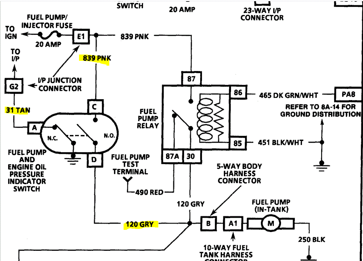
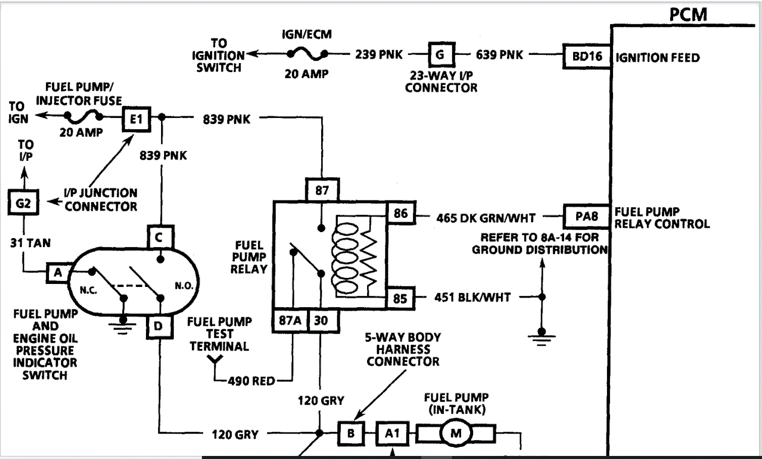
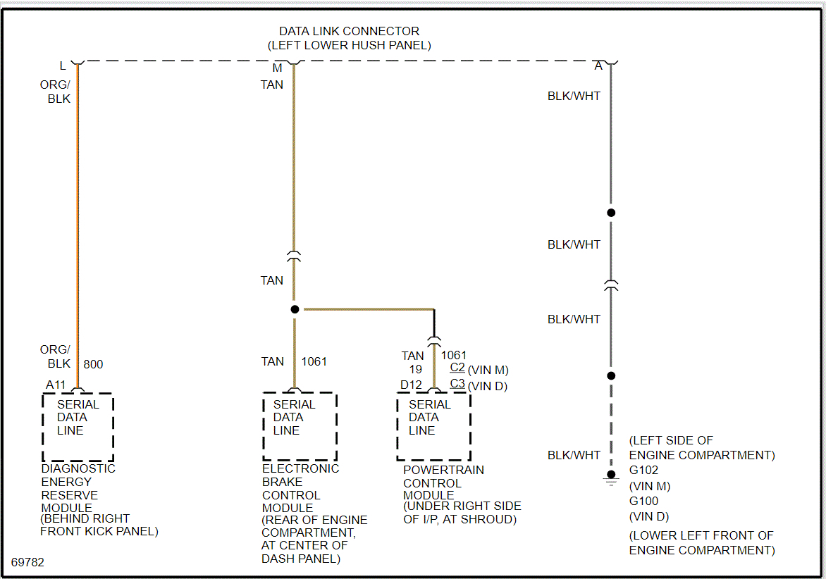
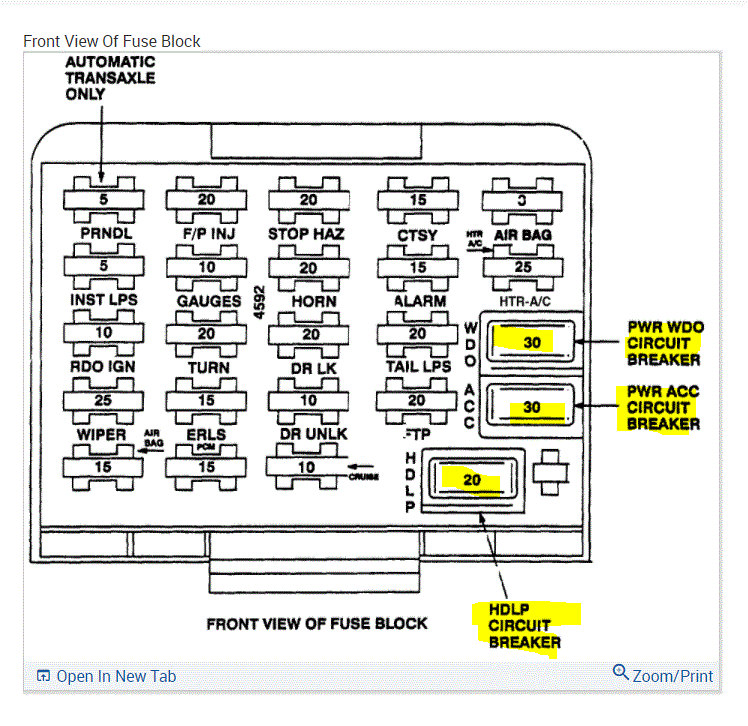
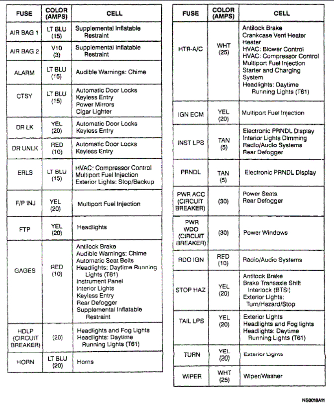
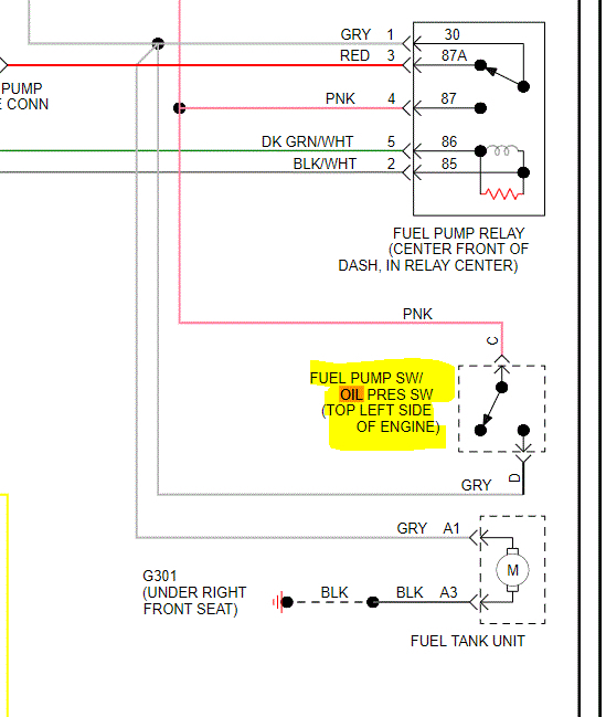
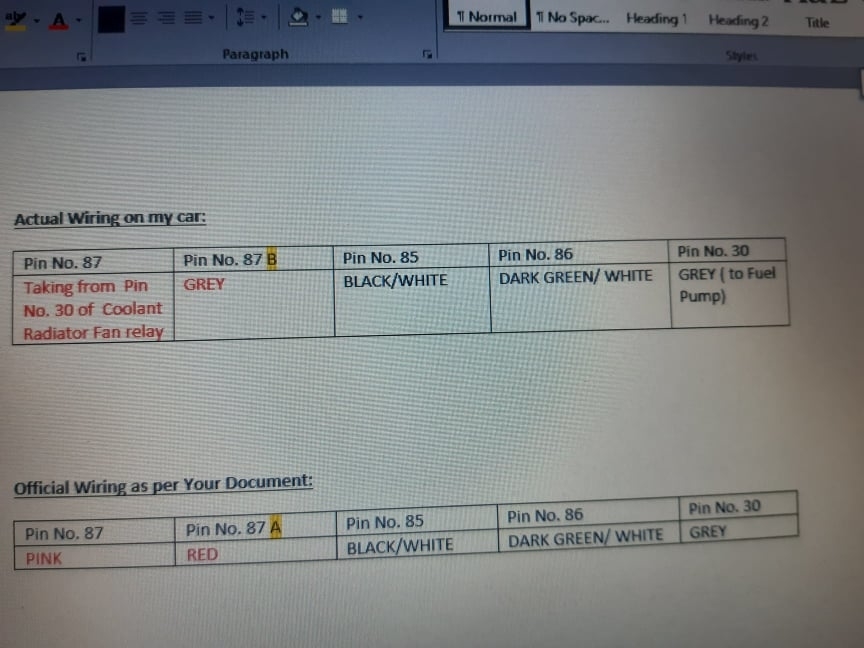
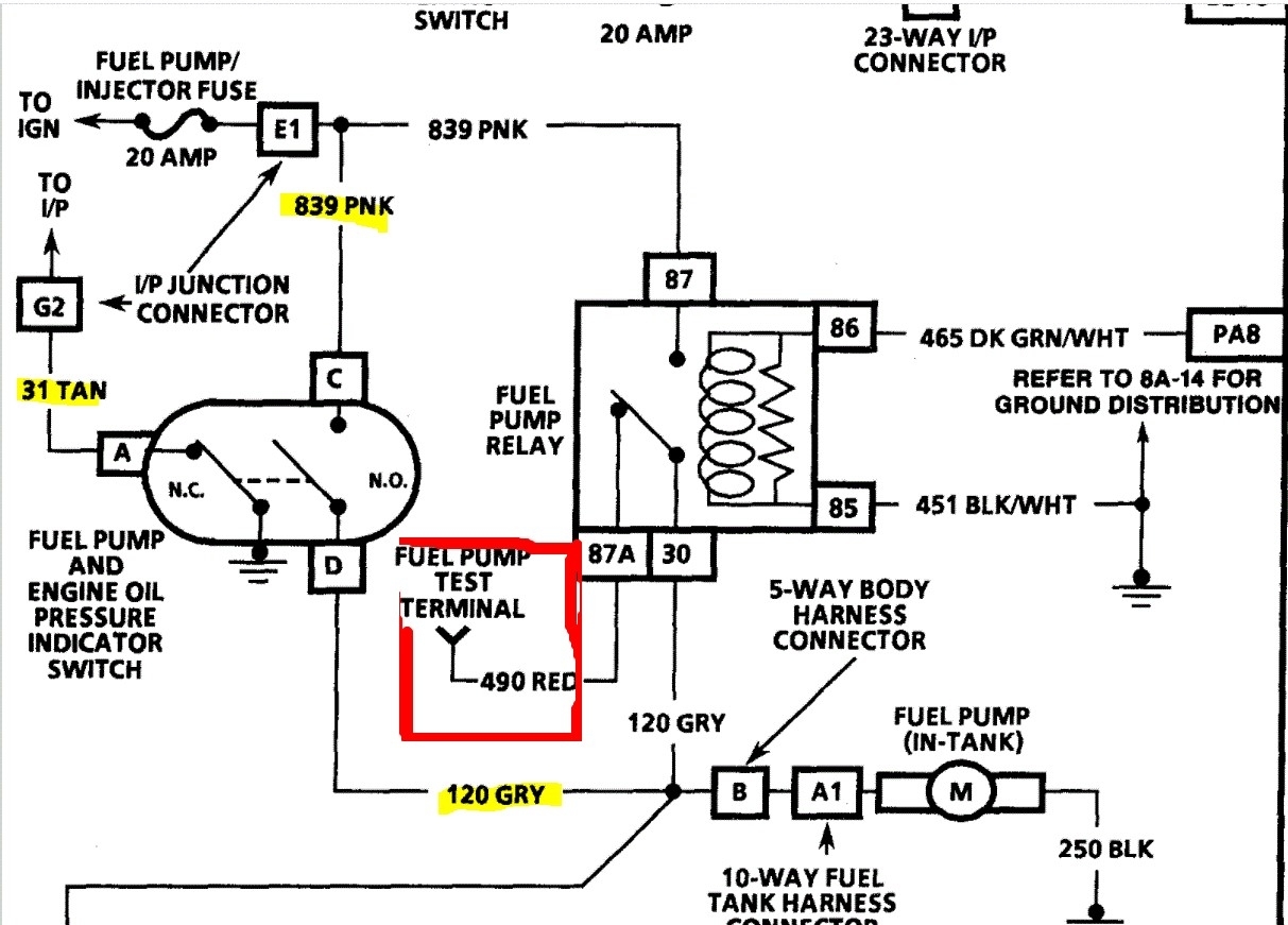
I also checked my Fuel Pump Relay as per the pins numbers and the colors of the wires attached to each pin. While the diagram received from you ( attached here) gave exact colors for corresponding pins( numbered)( for which I am very thankful to you ), my electrician seems to have gone for an alternate layout and as follows. The following is a comparison of the connection ( actual and as per the document attached):

Pins No. 30, 85 & 86 match your document . Only these two pins/wires have some issues:

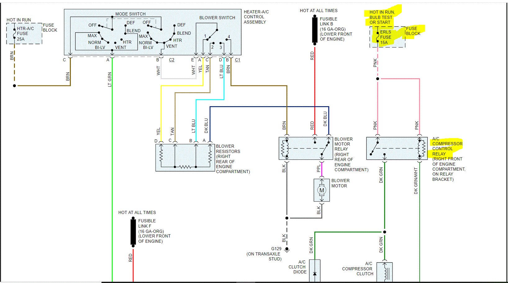
1. Pin 87: According to your schematic it should be connected to the (PINK) wire, my electrician paired it with the Pin No. 30 of the adjacent relay of the( Coolant Radiator Fan) because the pink wire used to lose LIVE signs from time to time causing sudden stalling for the engine, so that was his alternative to get the engine going all the time since he couldn't solve that puzzle of frequent stalling.

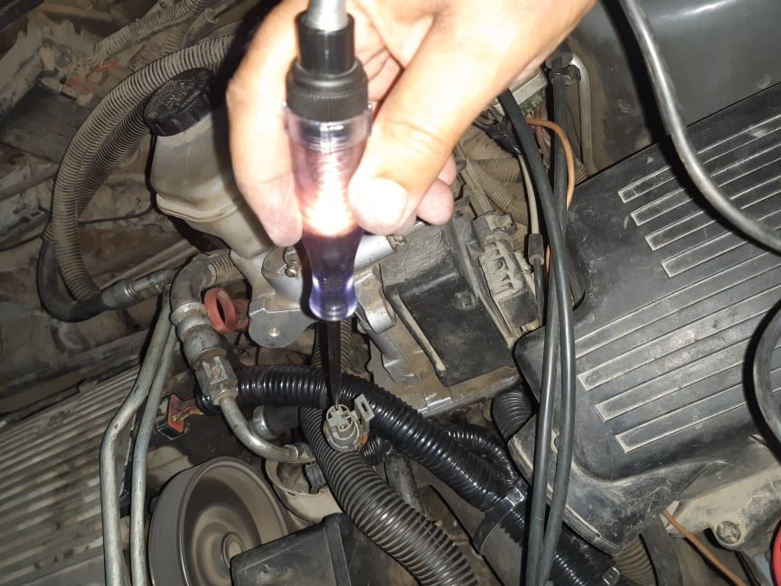
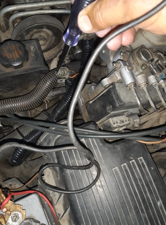
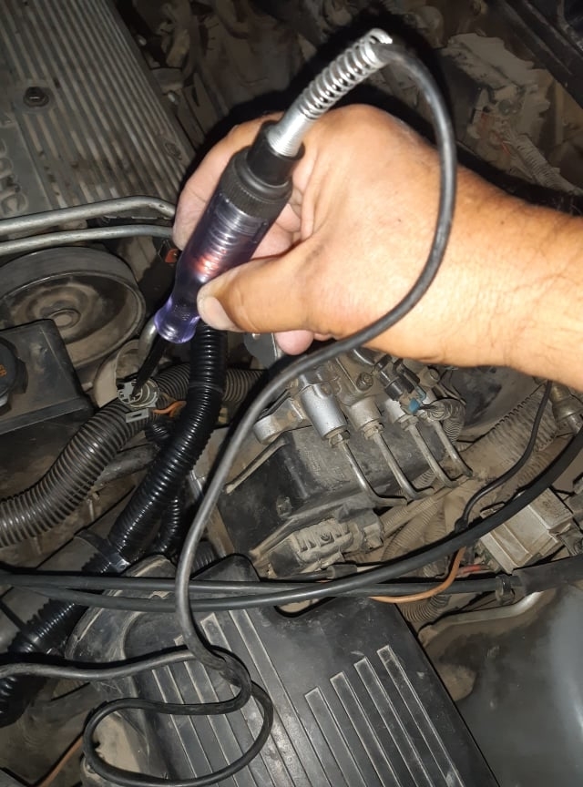
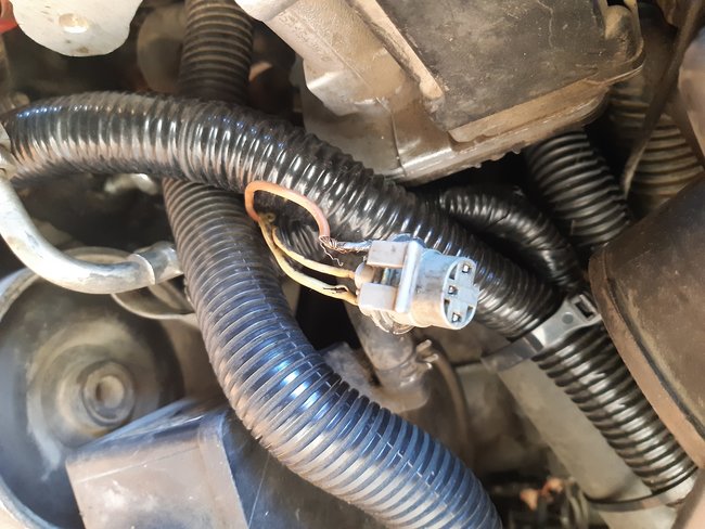
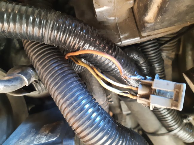
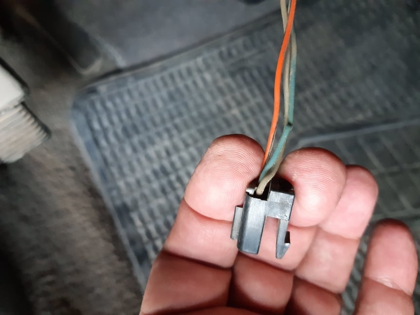
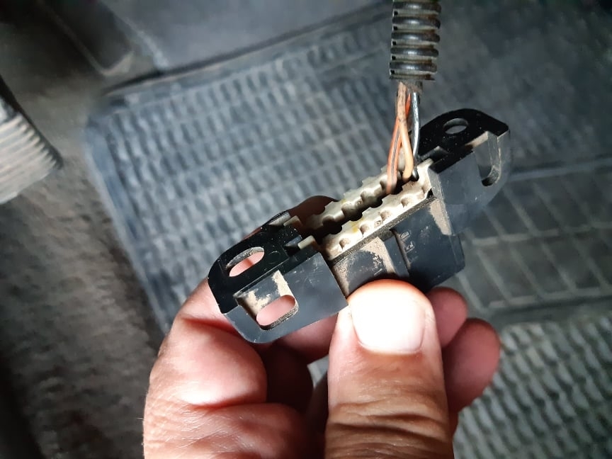
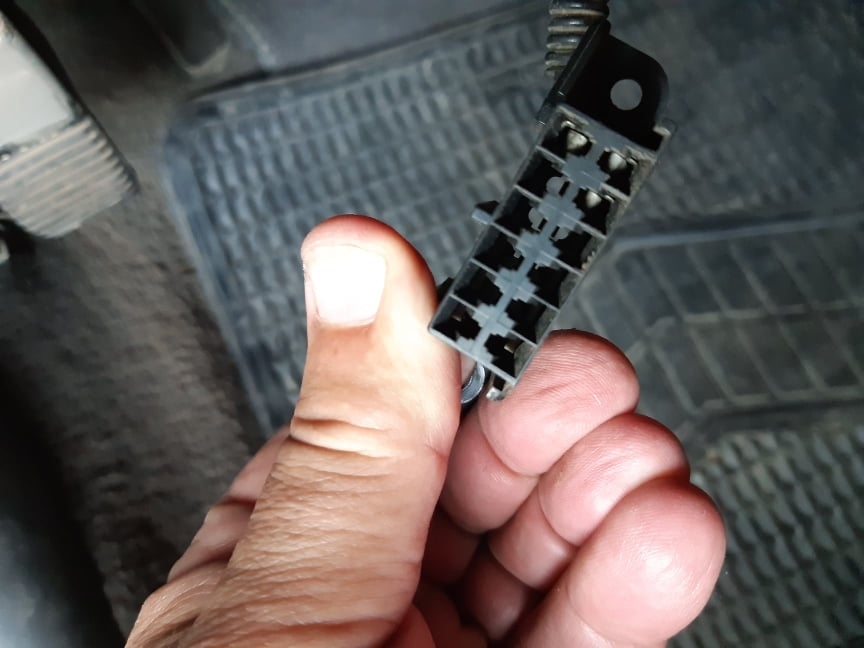
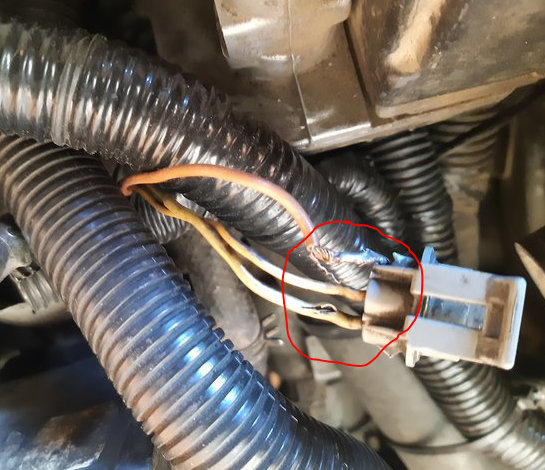
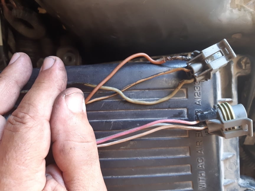
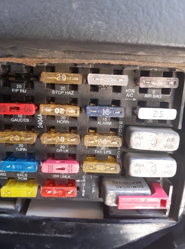
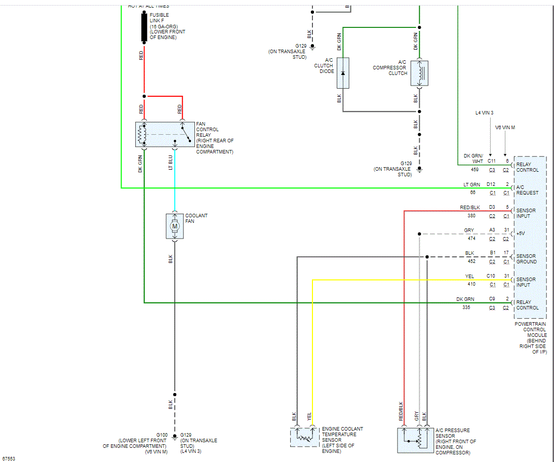
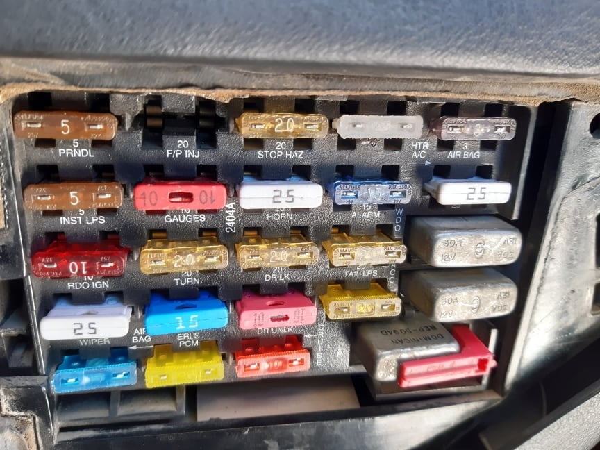
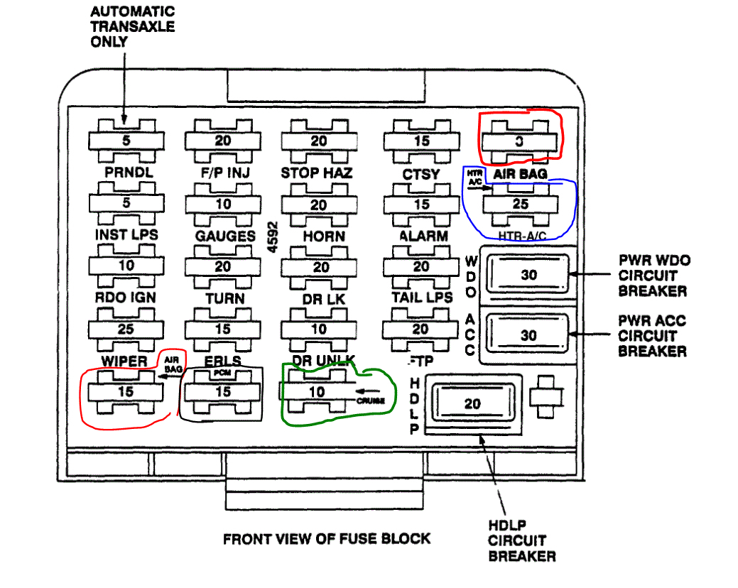
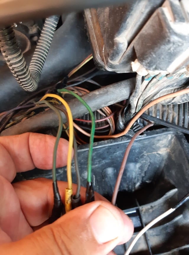
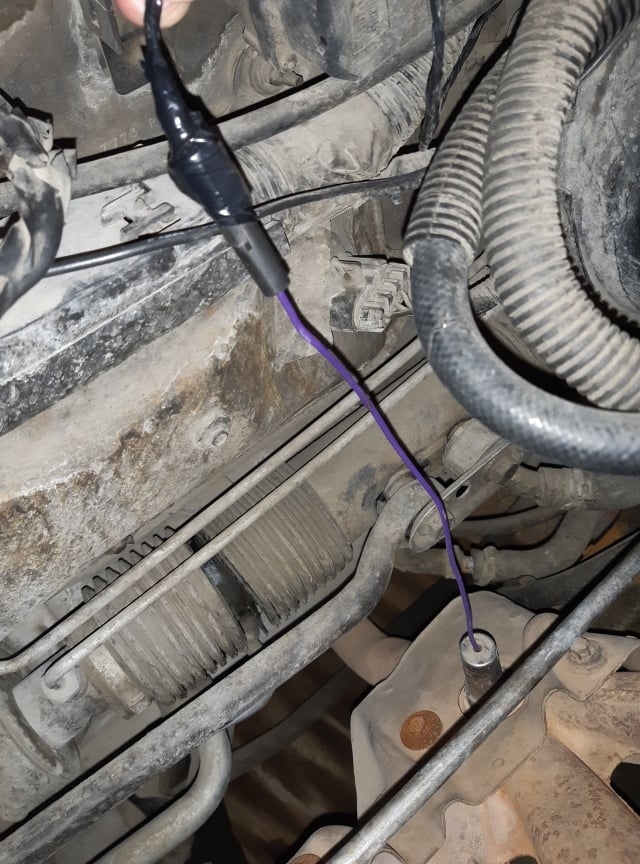
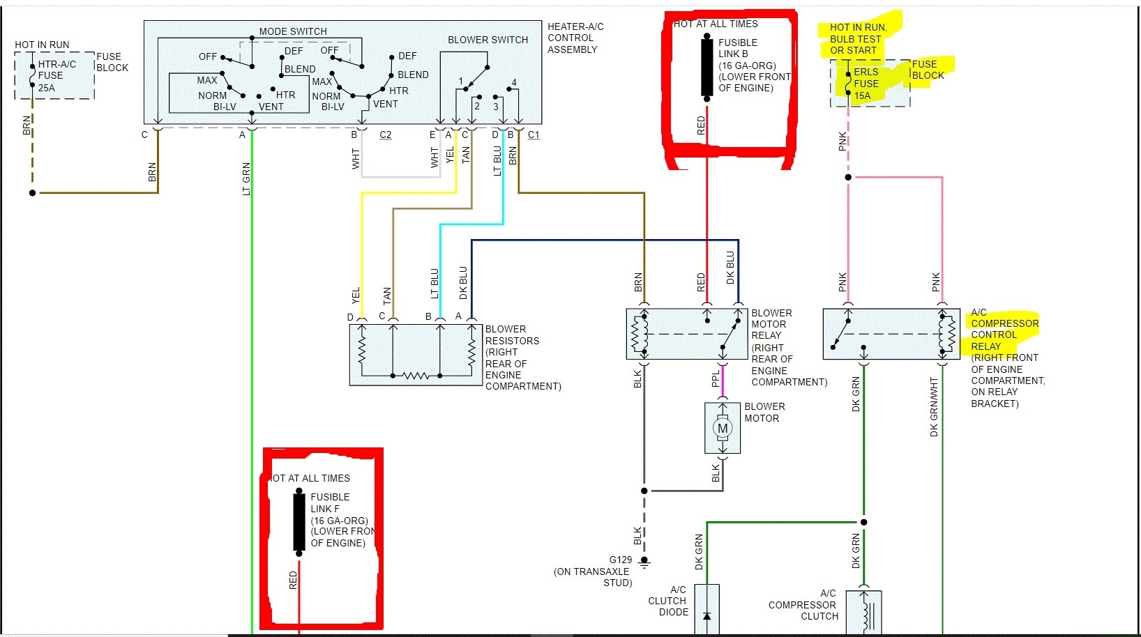
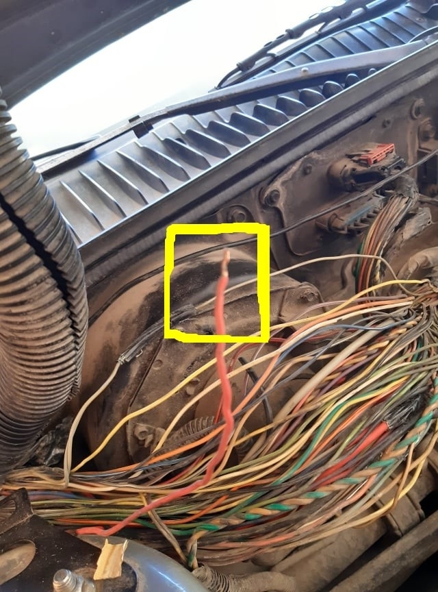
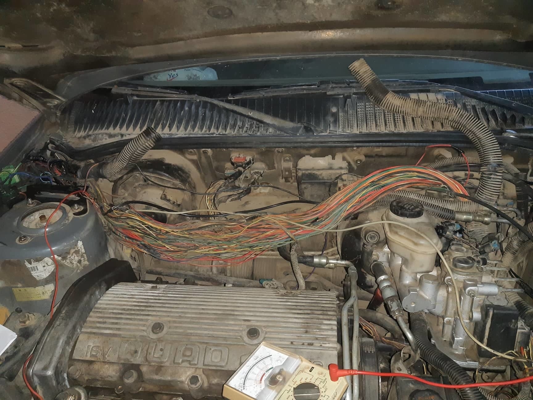
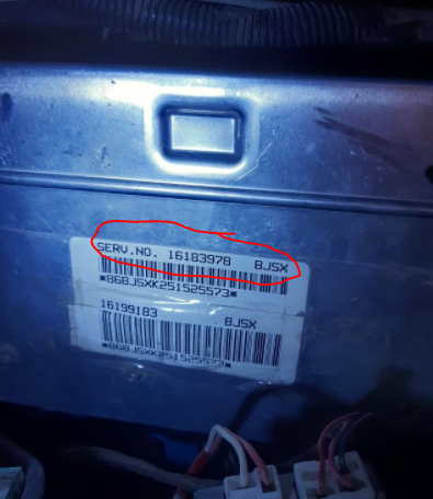
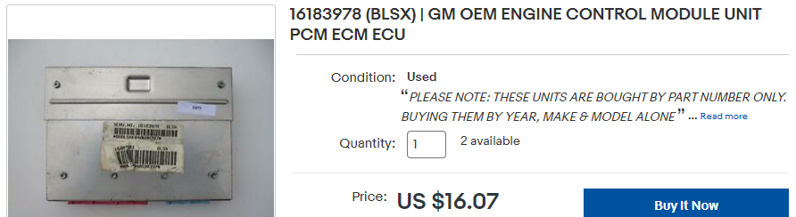
2. Pin No. 87 A (or B with me): Right now, it is connected to a (gray) wire coming all the way from that 3-wire connector of the Oil Pressure Switch/Fuel Pump Switch ( The Oil Pressure Switch fails to give any oil pressure reading on the gauge within the Instrument Panel, I replaced it twice but the problem is still the same). Again for the GREY wire, the lamp tester lights when the engine runs and it gets positive signal accordingly so the (Fuel Pump Relay) works alright. Needless to say, according to your schematic diagram, it should be connected to the (red) wire, but this wire has no electricity at all( seen in the 3rd attachment here. I am awaiting a clarification from your side to locate those two Fusible Links( shown in the 4th attachment) which may be the reason it went dead (hopefully) since they are part of the (red) wires and might have been disconnecting the circuit.
Jun 26, 2021 at 8:15 AM
Avatar
YASIRDAHHAM
  • MEMBER
  • 186 POSTS
Hi dear friends, this is an update worth bringing as I believe. The red wire turned out to be leading to a female clip , one of two clips used for testing the fuel pump and are both located in the left rear side of the engine compartment (Fuel Pump test terminal 490 red according to your schematic drawing attached here). I know now that pin 87B /87A is but for feeding another line/load using the same relay, it is not of any significance to my own case so please skip that part of my earlier post. The second image attached is for the harness that connects the 4 relays corner of the engine compartment to the rest of the compartment. This whole clutter is going to reveal something, hopefully.
Jun 27, 2021 at 1:11 PM
Avatar
YASIRDAHHAM
  • MEMBER
  • 186 POSTS
It pleases me to curtail this whole problem exchanges with the good news that I found the cause: The connector for the Injectors lines was found to be severely damaged with the insulation so brittle and missing in many locations. This was after I took off the insulation sleeve( that black serrated hose) near the base of the coolant radiator and brought the whole wires up to be examined one by one. Having done this and having committed to the proper wiring for the Fuel Pump Relay the engine is now working great, no (Check Engine Soon) warning light, no continuation of engine running after I be switching the Ignition Switch "off". I have to provide this testimonial, you were great, you led me right, encouraged me to take the lead and what electricians here always refused to do saying the problem is not due to this part. My earlier queries as per (what is this part?) are still valid in case you have answers, otherwise, he main problem had been resolved.
Jun 28, 2021 at 2:25 PM
Avatar
JACOBANDNICKOLAS
  • CERTIFIED EXPERT
  • 110,175 POSTS
Hi,

That is great news. I'm glad to hear you found the problem. Please feel free to come back anytime in the future if you have questions.

Take care,

Joe
Jun 28, 2021 at 7:47 PM
Avatar
YASIRDAHHAM
  • MEMBER
  • 186 POSTS
Your assistance has been so invaluable, the least detail and the simple schematic to you which was a gift to me. Bless you dear friend.
Jun 28, 2021 at 10:14 PM
Avatar
JACOBANDNICKOLAS
  • CERTIFIED EXPERT
  • 110,175 POSTS
You are very welcome. I hope you come back in the future if you need help.

You take care as well, my friend.

Joe
Jun 28, 2021 at 10:48 PM
Avatar
DANNY L
  • CERTIFIED EXPERT
  • 5,648 POSTS
Hello again.

I've re-attached your pictures below of the part you were looking to identify and circled in red. I've attached a picture of what I found below for that part number. I'm glad you were able to find and fix the problem. Hope this helps and thanks again for using 2CarPros. We hope you will use our site again in the future when needed.

Danny-
Jun 29, 2021 at 11:31 PM
Avatar
YASIRDAHHAM
  • MEMBER
  • 186 POSTS
Thanks a lot dear Danny, you contributed much to solving my problem(s). This very unit had been described a few years ago as being a control unit for the automatic transmission of my car. I always avoid going after what they say here and rather base my knowledge on credible sources like you and our friend Joe.
Jun 30, 2021 at 6:21 AM